42-Cell Battery Module Design
Mechanical Design / Battery Systems / FEA
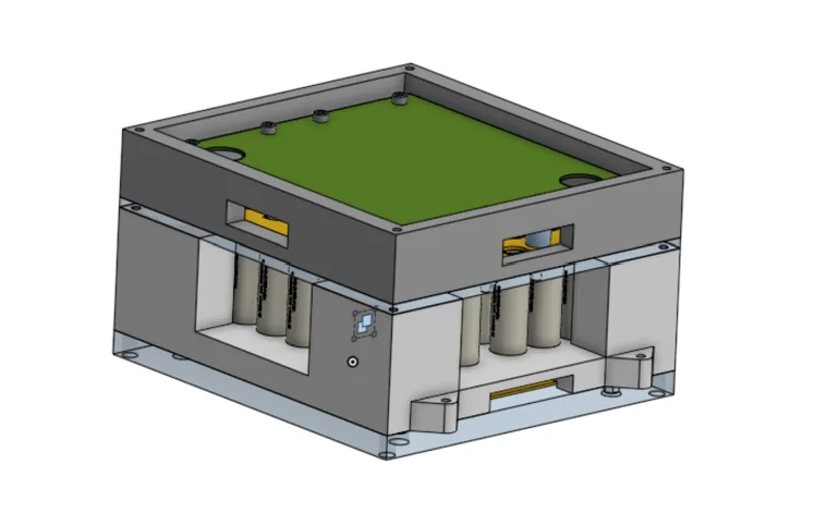
Packaging 42 cells as one mechanical system
I designed a 42-cell, 14S3P battery module in SolidWorks, with a nominal voltage of 50.4 V and capacity of 14.85 Ah. The work connected cell spacing and retention with structural loading, electrical insulation, BMS / Vsense integration, and practical assembly. The main tradeoff was fitting cells, supports, and electronics into a compact module while preserving clearance and a defined load path.
Electrical architecture sets the mechanical envelope
Cell retention, structure, and electronics in one stack
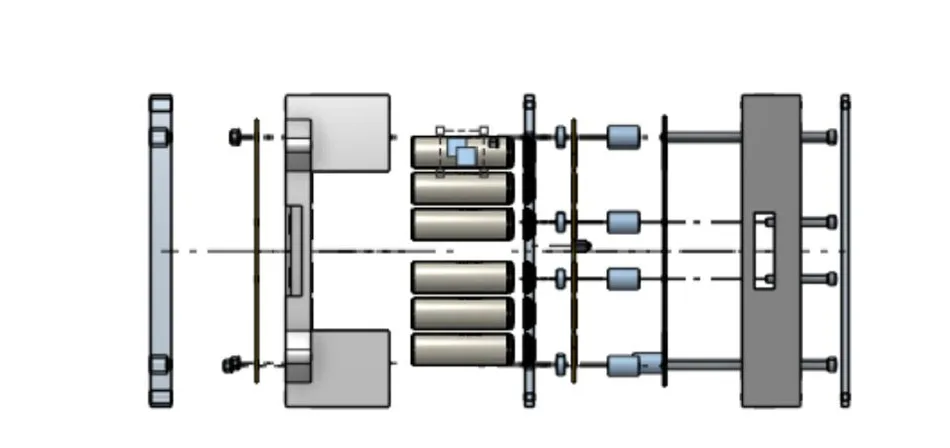
The assembly uses cell-locating plates, a surrounding cage, a base, insulation layers, and fastened interfaces. These components establish cell position and connect the internal assembly to the module mounts. Packaging the BMS and Vsense hardware alongside the cells required space for the boards, connectors, wiring, and mechanical attachment.
Why 14S3P?
The design target was approximately 50 V per module. Fourteen 3.6 V cells in series give 50.4 V nominal; three 4.95 Ah cells in parallel give 14.85 Ah. With the cell count fixed at 42, changing the series/parallel split trades voltage against capacity.
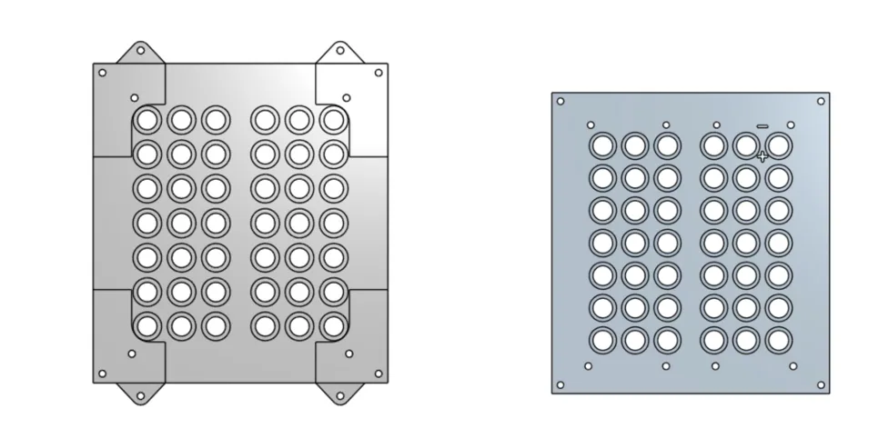
The locating plates establish the physical cell array. The electrical configuration is 14S3P; the pocket pattern alone does not describe the series connections.
| Configuration | Nominal voltage | Full-charge voltage | Capacity |
|---|---|---|---|
| 7S6P | 25.2 V | 29.4 V | 29.70 Ah |
| 14S3P — selected | 50.4 V | 58.8 V | 14.85 Ah |
| 21S2P | 75.6 V | 88.2 V | 9.90 Ah |
| 42S1P | 151.2 V | 176.4 V | 4.95 Ah |
All four configurations contain approximately 748.4 Wh of nominal cell energy.
Balancing clearance, cooling space, and packaging
I selected a 6 mm vertical cell gap, using published spacing research as a design reference. In that study, increasing the gap from 3 to 6 mm increased mass flow from 0.040 to 0.045 kg/s and reduced maximum cell temperature from 46.9 to 41.0 °C. A 9 mm gap reached 39.0 °C, illustrating the smaller additional thermal benefit of using more space.
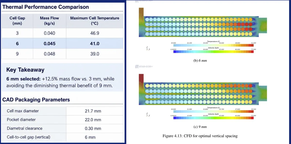
The CAD uses 22.0 mm pockets around a 21.7 mm maximum cell diameter, leaving 0.30 mm diametral clearance for insertion. Pocket clearance and the 6 mm inter-cell gap serve different purposes: one accommodates fit, while the other reserves space between cells.
Reference: Francesco Leotta (2020), Design of a battery pack for a Formula SAE racing car, Politecnico di Torino, §4.5, pp. 48–51. The published thermal results informed spacing selection; they do not establish this module’s thermal performance.
Protecting the electronics while preserving access
BMS / Vsense integration
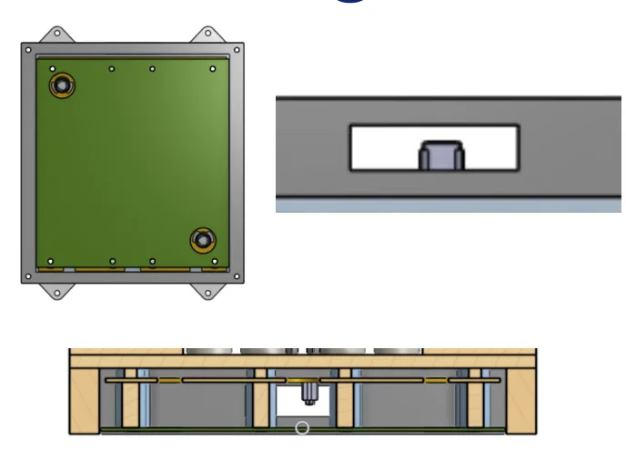
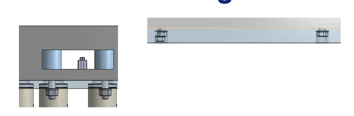
The BMS is packaged below the cell array, with clearance to the cells, top plate, and Vsense assembly. Openings face the connectors toward the module exterior for harness access.
Dedicated routing space accommodates Vsense, Tsense, and communication wiring. A PET-film insulation layer separates the BMS from the aluminum enclosure and other conductive parts.
Separate load paths for the cage and base
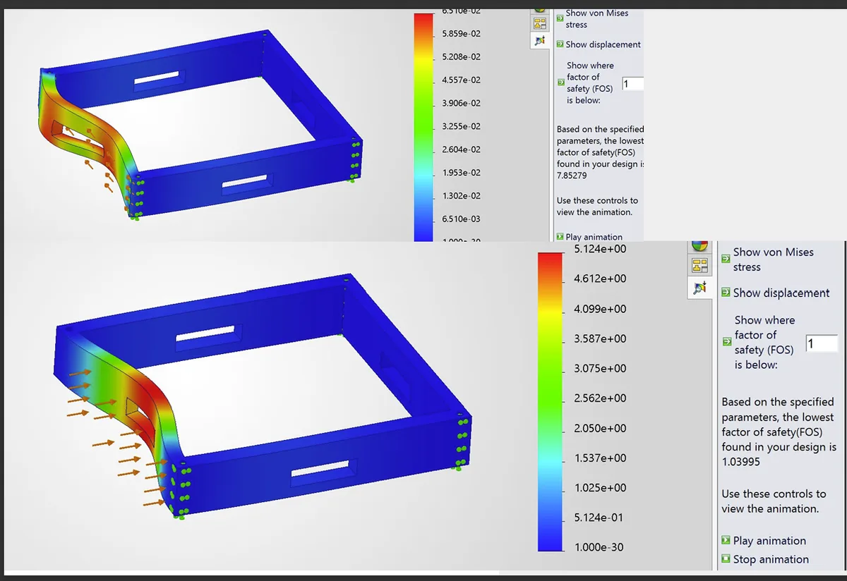
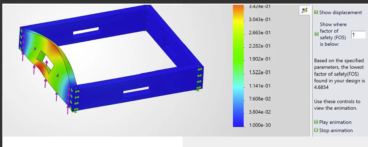
I evaluated 40g longitudinal and lateral loads and 20g vertical loads to assess the structure under inertial loading. The cage calculation uses the mass it supports; the base calculation uses the full modeled module mass. Applying F = ma gives the documented loads below.
| Analyzed component | Supported CAD mass | 40g · each horizontal case | 20g · vertical case |
|---|---|---|---|
| Cage | 3.208 kg | 1,260 N | 630 N |
| Base | 4.141 kg | 1,625 N | 813 N |
Cage response
Base response
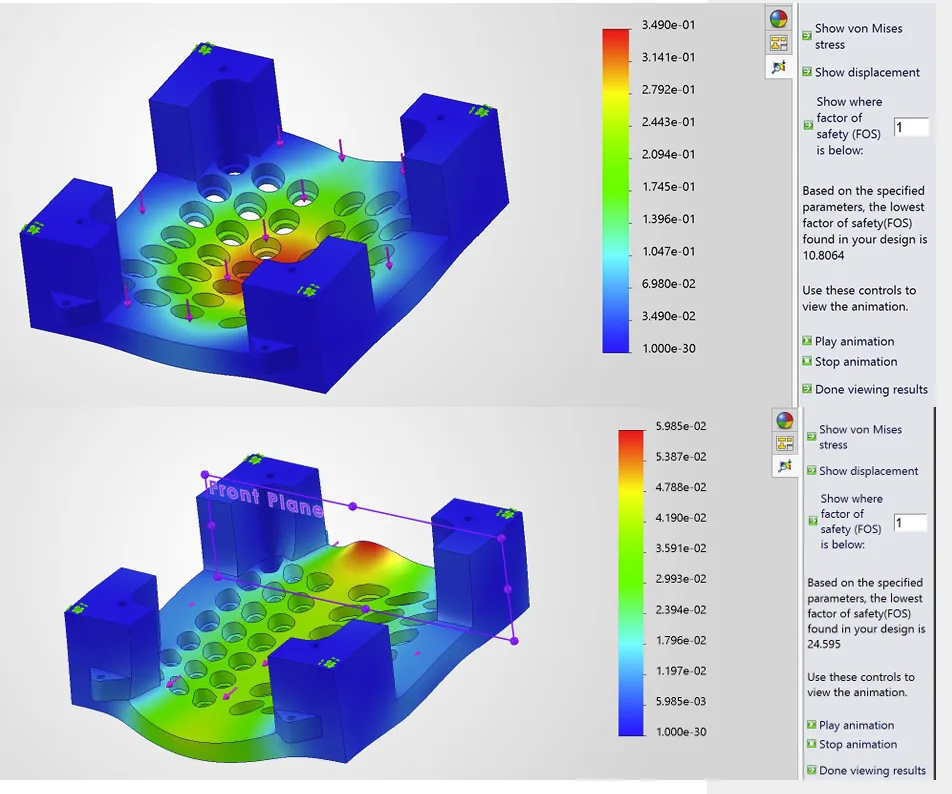
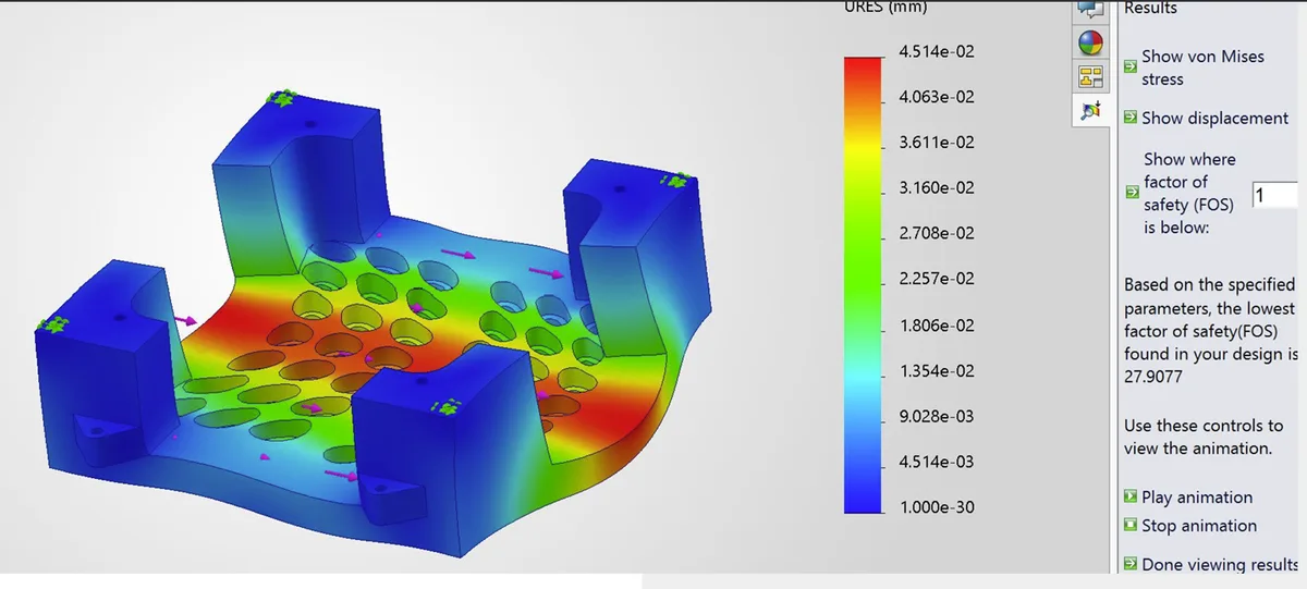
FEA provided a way to evaluate deformation and structural margin around openings, plates, and attachment points, guiding attention toward the load-bearing geometry during structural optimization. The documentation does not tie a specific geometry revision to a before/after FEA result, so no quantified improvement is claimed. The displayed deformation shapes are simulation visualizations; physical validation and a complete review of material, mesh, and joint assumptions remain outside this project’s scope.
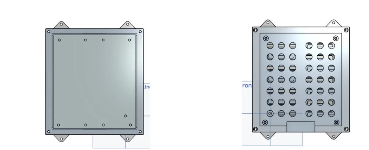
Three versions of the cell-end arrangement
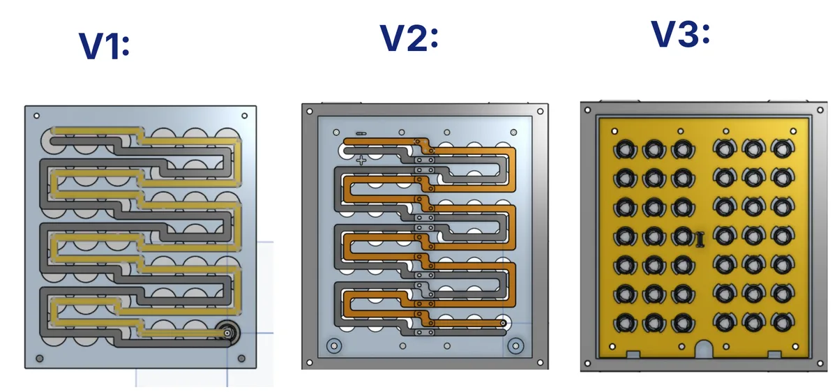
V1 and V2 show routed, strip-like features across the cell ends; V3 shows a plate with individual circular openings. These views document the layout evolution. The presentation does not specify the reason for each transition or a measured benefit, so the sequence is not presented as proof of a particular structural or electrical improvement.
Match the process to the part
The cell-locating and insulation views above show the repeated plate geometry; the exploded assembly shows the proposed insertion and fastening sequence. Separating planar plates from printed geometry keeps each part suited to its intended process. Manufacturing tolerances, printed-part properties, and joint retention would need verification before fabrication.
A complete module-level CAD design
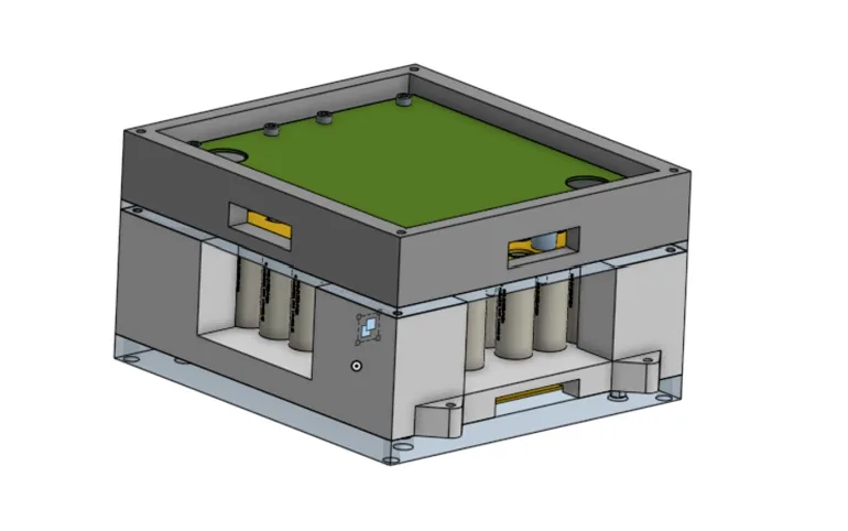
The final assembly combines the 42-cell 14S3P array, a cage and base evaluated at 20g and 40g, cell-locating plates, electrical insulation, and packaged BMS / Vsense hardware. The main decisions were selecting 14S3P for the voltage target, reserving 6 mm cell spacing, separating cage and base load calculations, and planning parts around machining and FDM processes.
What I learned
Battery-module design requires mechanical and electrical constraints to be resolved together. This project developed my approach to FEA-informed structural review, cell fit and spacing, insulation interfaces, electronics access, and process-aware part design.
My role: design, CAD, and analysis
I developed the SolidWorks module assembly, compared electrical configurations, selected the cell-spacing and pocket-clearance parameters, worked through structural and insulation details, packaged the BMS / Vsense interfaces, calculated inertial loads, and performed the cage and base FEA studies. I also documented the design revisions and proposed manufacturing methods. The thermal-spacing study cited above is external research. My work did not include physical manufacturing, battery testing, or module-specific CFD.