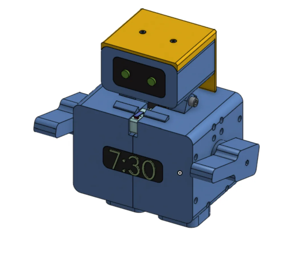
NOD: World’s First Mullet Alarm Clock
Mechanical Design · CAD · Kinematics · Electronics Integration · DFM
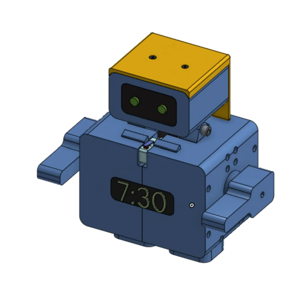
An alarm clock that moves as part of the interface
NOD is a character-driven mechanical alarm clock that combines mechanical motion, electronics, and physical interaction. The goal was not to hide a conventional digital alarm inside a robot-shaped enclosure. The head, latch, arms, OLED, and time-selection knob all take part in setting, activating, snoozing, and stopping the alarm.
The project brings together CAD, mechanical architecture, kinematic verification, first-principles force and torque analysis, FDM prototype planning, electronics integration, and a path toward production manufacturing.
This page is the condensed engineering story. The resource links above provide the complete 26-page technical documentation and the live Onshape assembly.
The character is the control surface
- Rotate the rear knob to select the alarm time.
- Read the selected time on the OLED.
- Push the head downward to confirm the time.
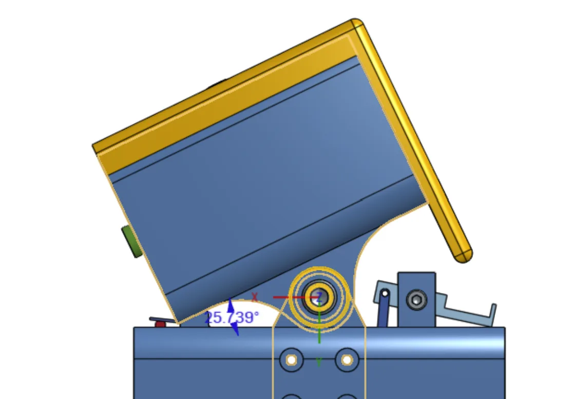
- The head stops and latches at 25°.
- At the selected time, the alarm activates and the latch releases the head.
- Press one articulated arm for a 10-minute snooze or the other arm to stop the alarm.
One expressive motion, built from compact mechanisms
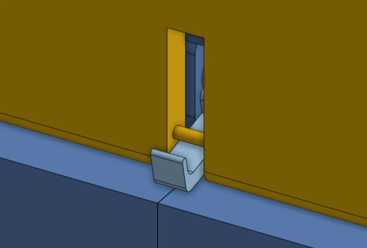
Spring-return head and passive latch
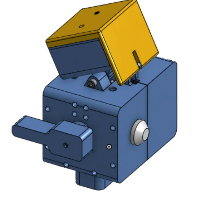
The head rotates through 25° about a fixed pivot. Pushing it down loads a return spring while a striker moves past the latch. The latch then returns to its locking position and retains the head without continuous actuator torque.
A mechanical backstop defines the upright position, while the striker-and-latch interface defines the lowered position.
Micro servo and printed linkage
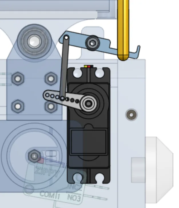
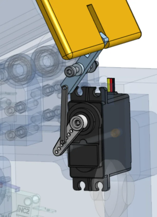
The MG90S-class metal-gear micro servo rotates the latch through a short printed linkage. This uses fewer components than a gear train, stays compact, and can be revised quickly during prototyping.
Articulated arm controls
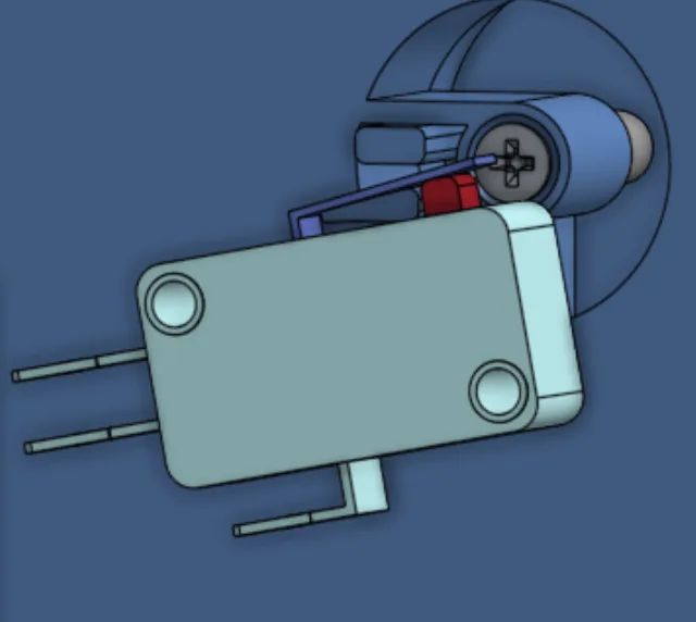
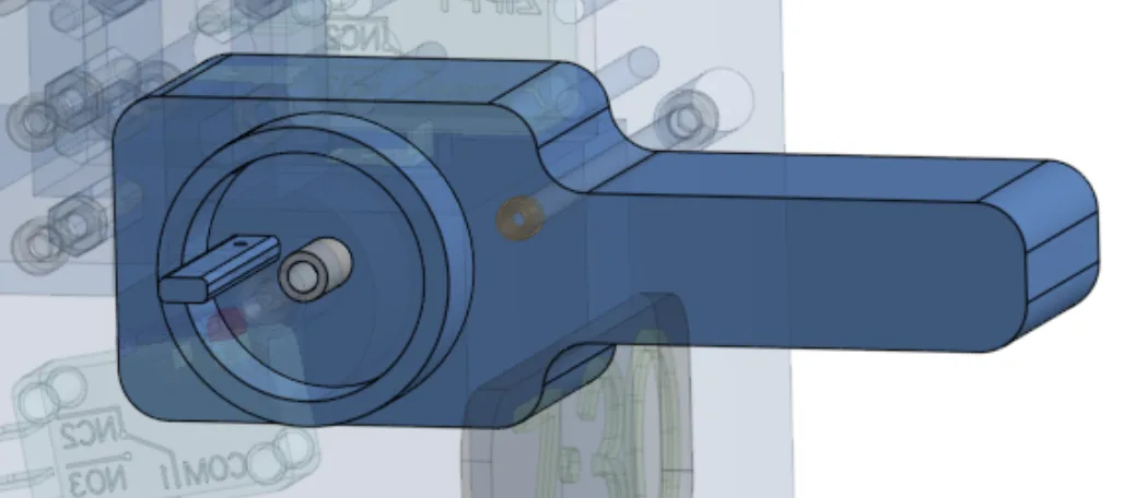
Both arms use the same pivot and spring-return architecture. Pressing an arm rotates it against its spring and actuates a microswitch; releasing it returns the arm to its resting position. The arms therefore serve as both character expression and snooze/stop inputs.
Split housing and moving display
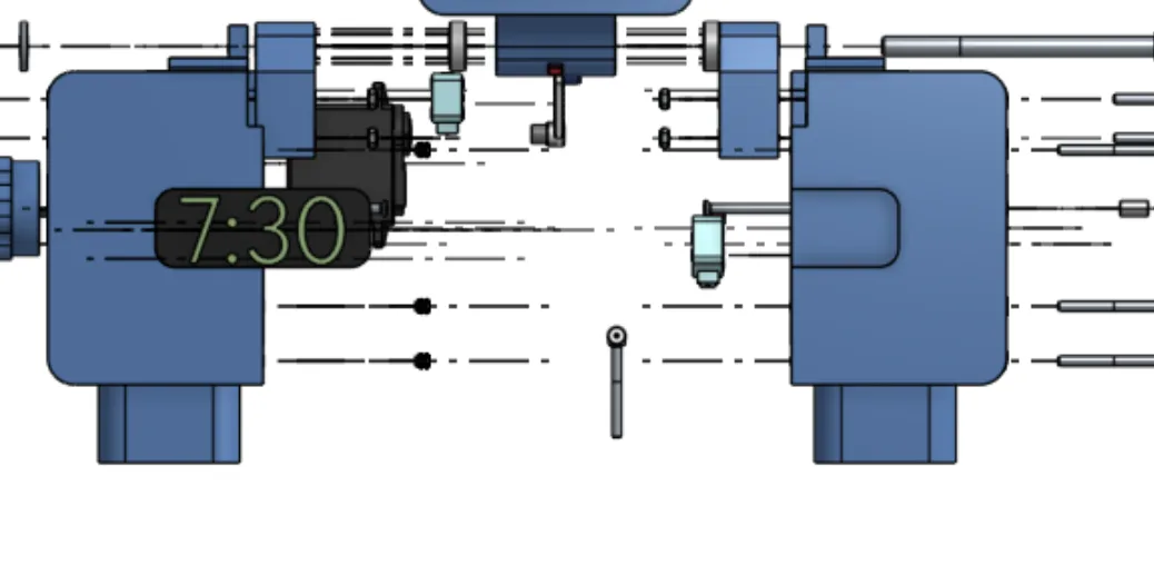
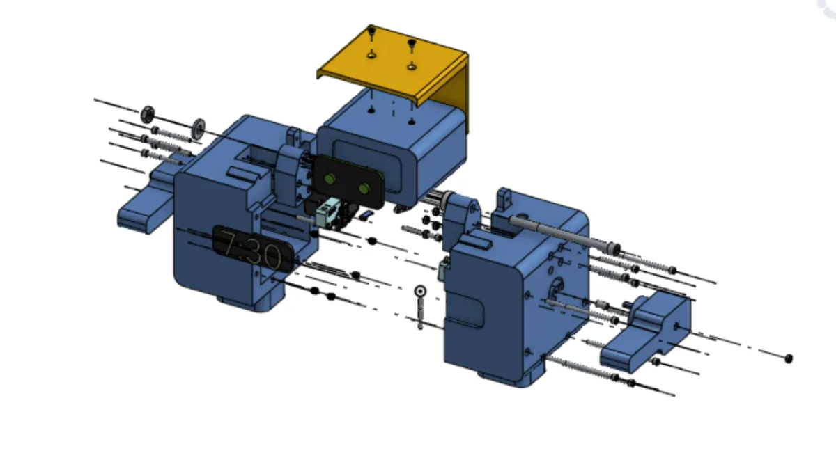
The left/right body halves use M3 fasteners and heat-set inserts so the enclosure can be opened repeatedly for assembly, testing, and component replacement.
The servo and control electronics stay in the stationary body to minimize moving mass. Only the OLED and its required wiring move with the head, using a dedicated internal wire channel to avoid the mechanism.
Architecture selected around reliability and interaction
Verifying motion and sizing the actuator
A master mechanism sketch established the fixed servo and latch pivots, the locked 25° state, and the released 0° state. The fixed-length linkage was checked through both positions for full latch engagement, sufficient release travel, and interference with the striker, body, and servo.
| Result | Engineering meaning |
|---|---|
| 0.481 lbf·in | Maximum gravitational torque at 25°; the head-return spring must provide at least this restoring torque. |
| 0.664 lbf | Estimated striker force at the latch; this is the design load for the latch, pivot, and adjacent body ears. |
| 0.318 lbf·in | Calculated servo torque required through the measured latch and horn geometry. |
| 1.74–1.91 lbf·in | Approximate capability of the selected MG90S-class servo, providing substantial static torque margin. |
These are simplified static calculations. Friction, latch contact behavior, spring tolerances, and dynamic loads remain part of physical validation.
Designed to iterate now and manufacture later
Concentrated loads occur around the latch, M3 latch pivot, body ears, striker, and linkage. The design adds material around the pivot, uses filleted transitions, gives the latch a dedicated striker, defines travel with mechanical stops, and keeps the linkage short to limit bending.
PETG is specified for the FDM prototype because it offers more toughness and repeated-load resistance than PLA while remaining practical to print. Separate head, body, latch, arm, and linkage parts allow one mechanism to be revised or replaced without rebuilding the full product. M3 fasteners and heat-set inserts support repeatable assembly and servicing.
For production, the proposed architecture transitions the primary housing to injection-molded PC-ABS and the repeatedly loaded latch to PA Nylon. Production refinement would add controlled wall thicknesses, draft, fillets, and a defined parting line before tooling.
Validation required before design freeze
The CAD and calculations establish the intended architecture; the following physical validation work remains before production:
- Confirm repeatable head travel, latch engagement, and latch release between 0° and 25°.
- Select and cycle-test the head and arm return springs.
- Validate servo travel, linkage motion, torque margin, friction, and contact behavior.
- Confirm both arm-mounted microswitches actuate and reset reliably.
- Integrate the OLED, microcontroller, knob, switches, servo, power, and alarm-control software.
- Check that the OLED wiring clears every moving mechanism throughout head travel.
- Run repeated operating cycles to identify wear, loosening, or loss of function.
- Validate prototype tolerances, assembly time, and production-critical interfaces before tooling.
Each mechanical, electrical, system, reliability, and manufacturing gate must pass before design freeze.
Mechanical engineering expressed as product behavior
NOD combines a spring-return head, passive striker-and-latch retention, servo-operated linkage, articulated arm controls, OLED feedback, and a modular split housing into one character-driven alarm interaction. The result is a product concept in which mechanical engineering, electronics, assembly, and personality support the same user experience.