Deployable Multi-Level Climbing Mechanism
Mechanical Design · CAD · FEA · FRC
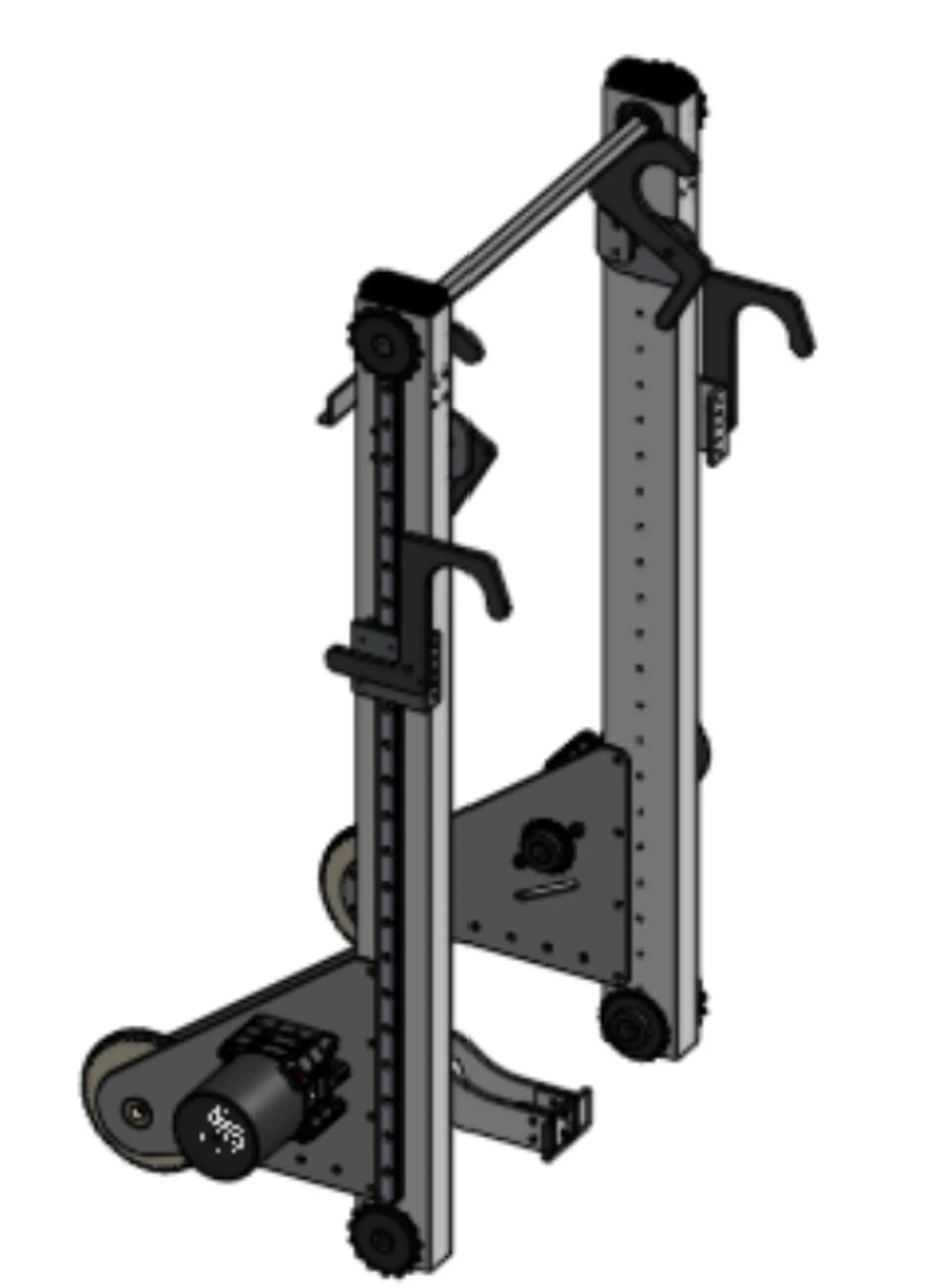
Climbing multiple bars, carrying the whole robot
I designed a custom deployable climbing mechanism for our 2026 FIRST Robotics Competition robot to complete the multi-bar endgame climb. The system uses alternating static and moving hooks to sequentially ascend multiple horizontal bars while staying inside strict FRC size, weight, and timing constraints.
I was responsible for the mechanical design, CAD, and the engineering decisions behind the mechanism.
The constraint that shaped everything
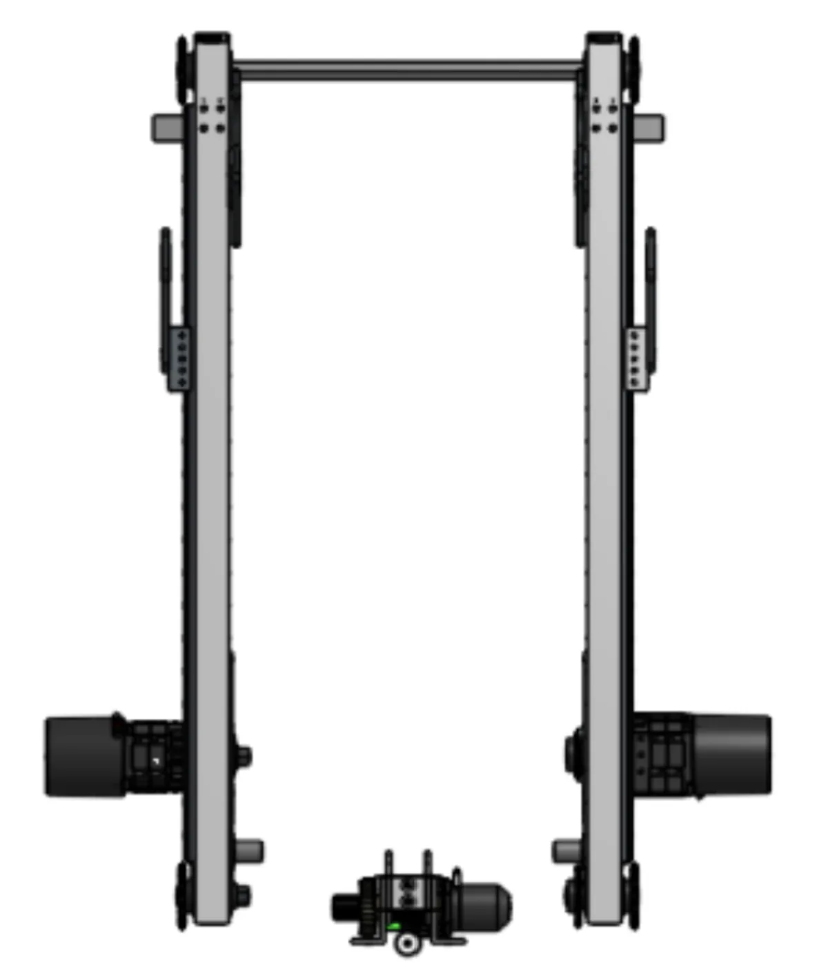
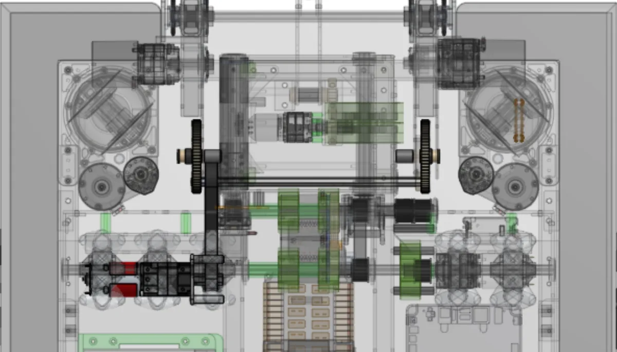
The climber had to start completely inside the robot frame perimeter, reach a first bar 27 in. above the floor without exceeding the 30 in. extension limit, and fit into the gaps between the swerve drives, drivebase, and shooter — about three inches of width on each side.
Everything else — the pivot architecture, the transmission split, the hook geometry — follows from packaging a full-robot-weight load path into that space.
What the mechanism had to do
| Requirement | Detail |
|---|---|
| Function | Complete the 2026 FRC multi-bar climbing challenge |
| Load | Support the full weight of the robot while climbing |
| Weight | Remain under the FRC robot weight limit of 115 lb |
| Start position | Begin completely inside the robot frame perimeter, per game rules |
| Extension | Stay within the 30 in. maximum extension while reaching a first bar 27 in. above the floor |
| Packaging | Fit between the swerve drives, drivebase, and shooter — 3 in. on each side |
| Schedule | Design, manufacture, assemble, and test within the team’s 3-month build season |
Pivot, transmission, and load path
Dead-axle pivot
The climber pivot experiences some of the highest loads on the robot while operating in a very constrained packaging envelope. I selected a dead-axle pivot because it provides a rigid load path while simplifying the bearing arrangement. That architecture also let the drivetrain be split into two power-reduction stages, reducing the amount of reduction required in the motor gearbox.
Power transmission
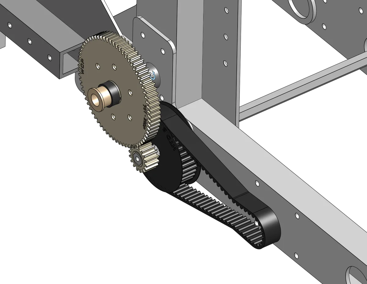
The pivot is driven by a belt reduction between the motor and an intermediate shaft, followed by a gear reduction from that shaft to the climber pivot.
The belt stage was selected because the expected loading did not justify a chain drive, and belts allowed predictable center-to-center spacing with minimal tensioning requirements. The gear stage provided a compact way to transfer torque within the limited packaging space available around the pivot.
The climbing motion itself is driven by chain — it has to support the full weight of the robot during ascent.
Hooks
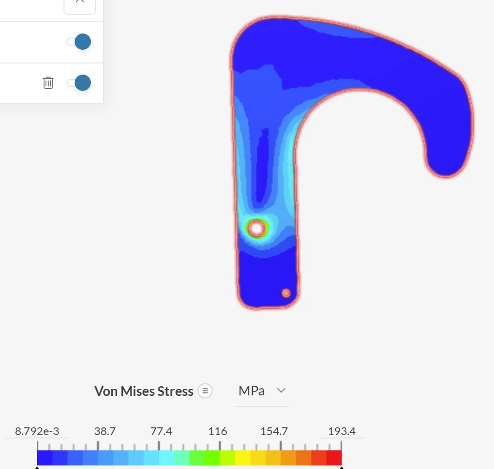
The mechanism uses alternating static and moving carbon fiber hooks to climb multiple bars sequentially. Carbon fiber was selected to minimize weight while maintaining enough strength to support the robot. I performed minor finite element analysis (FEA) during the design process to evaluate the structural performance of the hook geometry.
Structural design
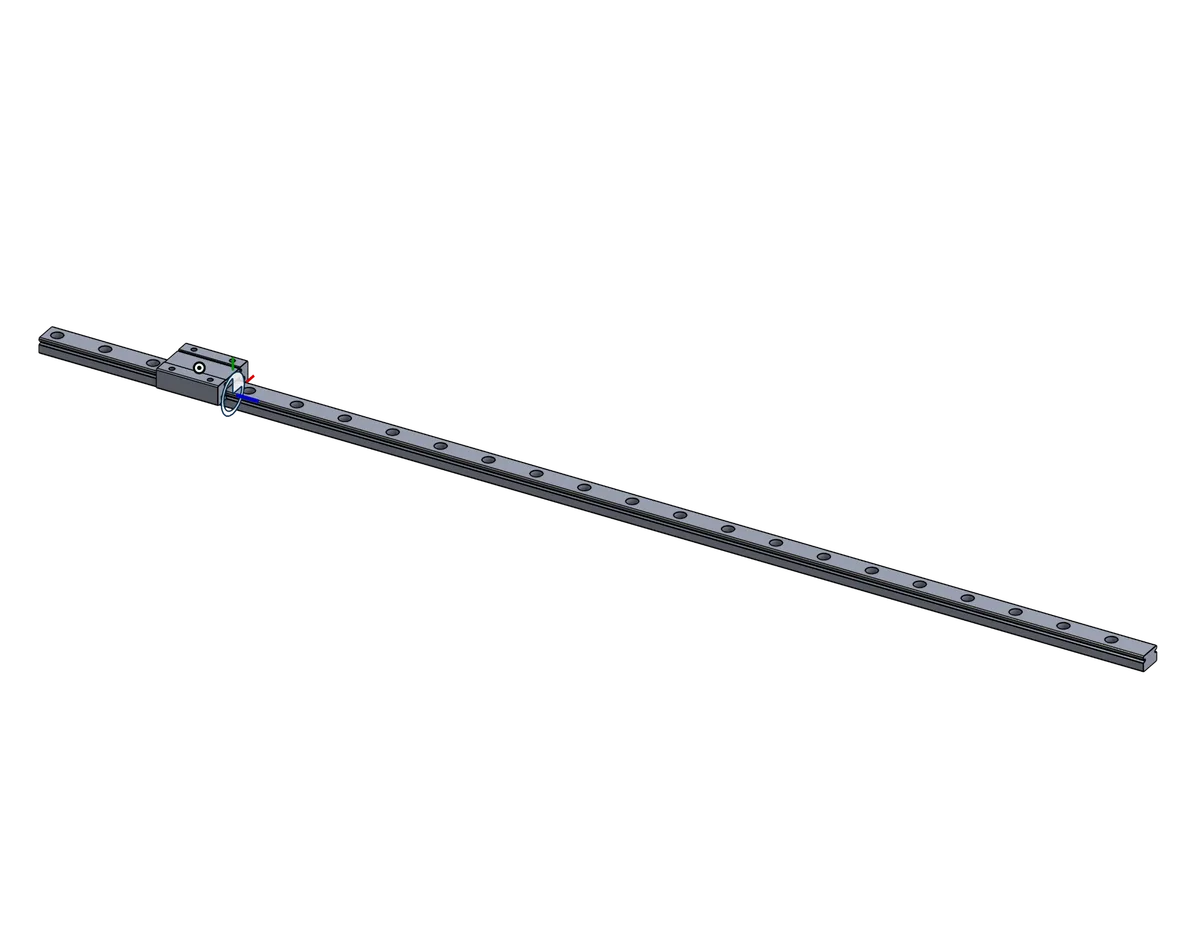
Linear rails and elevator bearing blocks were selected because they are rated to withstand the large horizontal loads generated when the climber pivots under the robot’s weight. Heavy components, including motors, were intentionally packaged as low as possible in the robot to maintain a low center of gravity and improve climbing stability.
Testing the hook interaction
During testing, relying on passive hook operation proved unreliable — the hooks did not consistently disengage and advance to the next bar.
I added a servo-actuated hook retraction system to actively retract the hooks during the climbing sequence.
Reliable hook retraction as part of the climbing sequence instead of depending on passive motion.
The static hook geometry had to meet the game's height requirements while still letting the hooks reliably disengage and advance to the next climbing bar.
Extensive iterative testing on the static hook geometry, supported by FEA on the hook structure.
A hook geometry that satisfies the height requirement and releases predictably during the sequence.
Off the screen and onto the bench
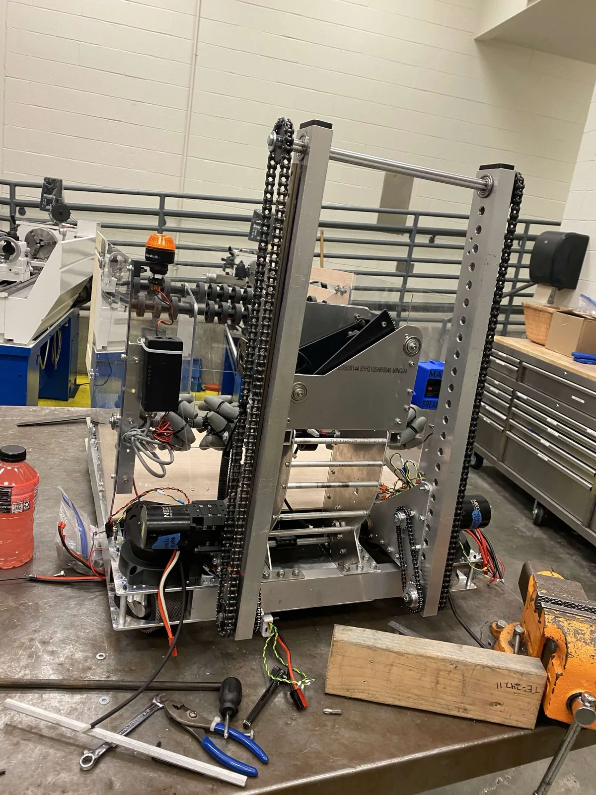
The mechanism as assembled: the two linear rails and bearing blocks that take the horizontal load, the chain runs that carry the robot’s weight during ascent, and the motors packaged low in the chassis.
The complete assembly had to be designed, manufactured, assembled, and tested inside the team’s three-month build season.
What I would do differently
This project reinforced the importance of balancing mechanical performance, packaging constraints, manufacturability, and overall robot weight.
If I were to redesign the mechanism, I would:
- Focus on reducing mass earlier in the design process
- Simplify the hook architecture
- Validate critical climbing interactions through earlier prototype testing