Three-Stage Cascading Elevator
Mechanical Design · CAD · Manufacturing · FRC
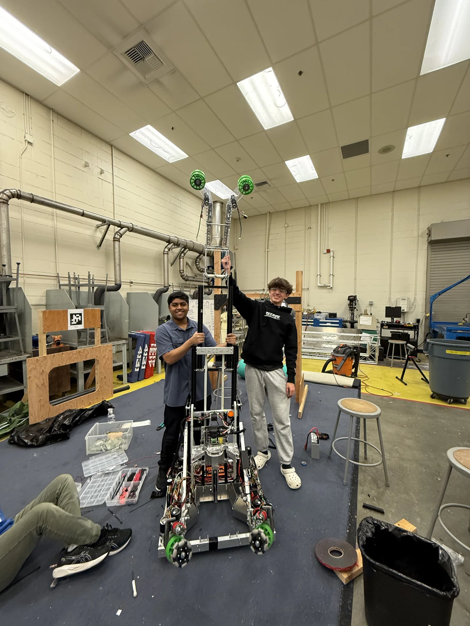
A moving target, mid-season
I designed and manufactured a three-stage cascading elevator for an FRC competition robot, spending 300+ hours designing, fabricating, assembling, testing, and iterating the mechanism.
The elevator was originally developed for the 2025 FRC game to position a coral game piece at different scoring heights on the reef. During development, the team’s strategy changed from scoring coral to scoring algae on the high net — the mechanism now had to reliably reach a single target roughly 7 ft above the ground.
That change reshaped the mechanical requirements. Instead of optimizing for multiple scoring heights, the elevator and its pivoting end-effector could be optimized around one high target, while still living inside the robot’s 3 ft 6 in. starting-height and 115 lb total weight constraints.
My role
I performed the design, CAD, assembly, and testing of the elevator. Other team members assisted with manufacturing.
The result
The completed elevator was integrated into the competition robot and used as part of the final robot architecture. The single-motor configuration provided sufficient lifting performance while saving weight against the original two-motor design.
What the mechanism had to do
| Requirement | Detail |
|---|---|
| Starting height | Fit within the 3 ft 6 in. robot starting-height limit |
| Weight | Keep the complete robot under the 115 lb FRC weight limit |
| Vertical reach | Score algae into the high net approximately 7 ft above the ground |
| Original scope | Support multiple coral scoring heights on the reef |
| Motion | Provide synchronized motion across all three stages |
| Structure | Maintain sufficient rigidity and belt tension under load |
| Packaging | Fit within the limited packaging space of the competition robot |
| Manufacturability | Be manufactured, assembled, and serviced with available team equipment |
Mechanical architecture
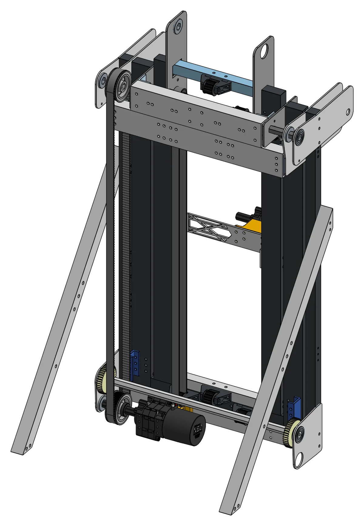
Three-stage cascading extension
The elevator used three stages to achieve the required vertical reach while keeping the robot within its starting-height constraint. The original design included a carriage contained within the third stage, intended to carry the coral scoring end-effector. After the strategy change, the carriage was removed and the mechanism was adapted around the new scoring configuration — the final system relied on the elevator’s vertical extension combined with a pivoting arm to reach the ~7-ft target.
Belt-driven cascading system
The elevator used a fully belt-driven cascading system, with the stages mechanically connected through the belt rigging:
- The first stage was clamped to the static frame.
- The second stage was clamped to the first stage.
- The third-stage carriage was clamped to the second stage.
This let the stages extend together while staying synchronized.
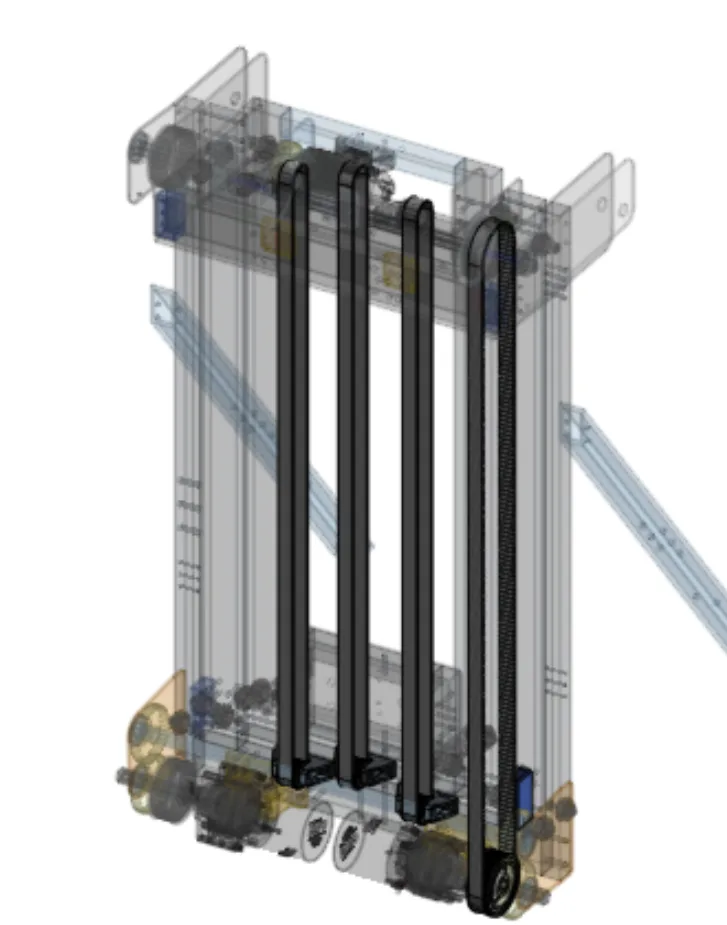
Two motors → one. The elevator was originally intended to use two motors with a synchronization shaft connecting the two sides. During development we determined that a single motor provided sufficient performance while reducing weight. The final elevator was driven by one motor through a 20:1 gear ratio, with the original synchronization shaft repurposed to mechanically drive both sides — saving weight for other robot subsystems.
Structural design and packaging
The elevator was built around aluminum V-slot extrusion, which let me mount custom bearing blocks and other components directly to the extrusion while keeping adjustability during assembly. The extrusion-based architecture made it easier to position and adjust components, install custom bearing blocks, slide components in during assembly, and modify individual parts without redesigning the whole elevator.
Packaging mattered especially here: the elevator had to stay inside the 3 ft 6 in. starting-height constraint while still extending far enough to reach the high scoring target.
What broke, and what I did about it
Most of the major problems came from component interference, belt tension, or localized structural loading. Rather than treating the elevator as one fixed design, I iterated individual components as problems emerged during testing.
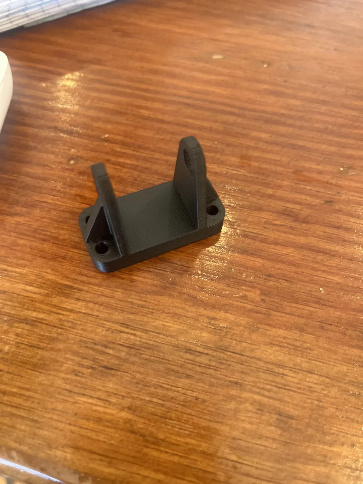
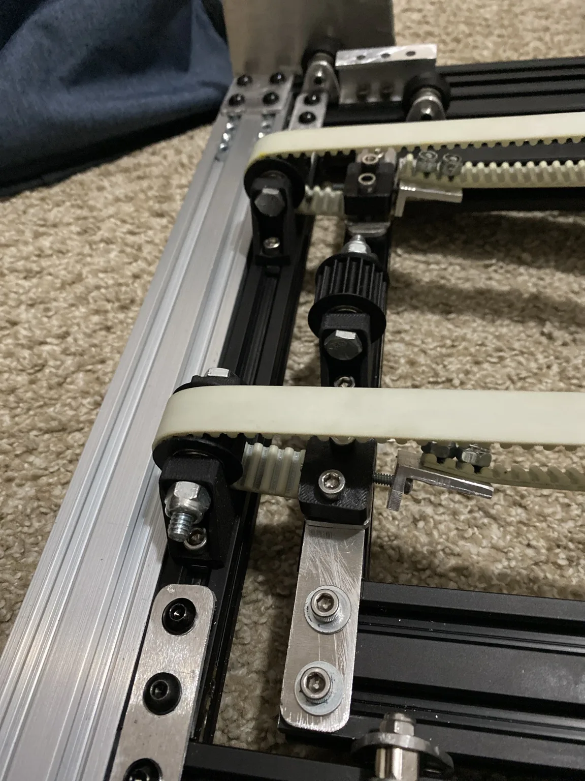
The inner-stage belts were originally tensioned with a cable clamp that had to be manually pulled into position. It was difficult to adjust and occupied too much space.
I redesigned the tensioner around a 3D-printed component with a press-fit locknut and threaded adjustment screw; tightening the screw pulls the belt into tension. For the outer-stage belts I used a simpler method — zip ties connecting the belts, pulled together to generate tension.
Substantially better adjustment and repeatability than the cable clamp. The belts stayed tensioned enough to lift the stages while keeping both sides of the elevator synchronized.
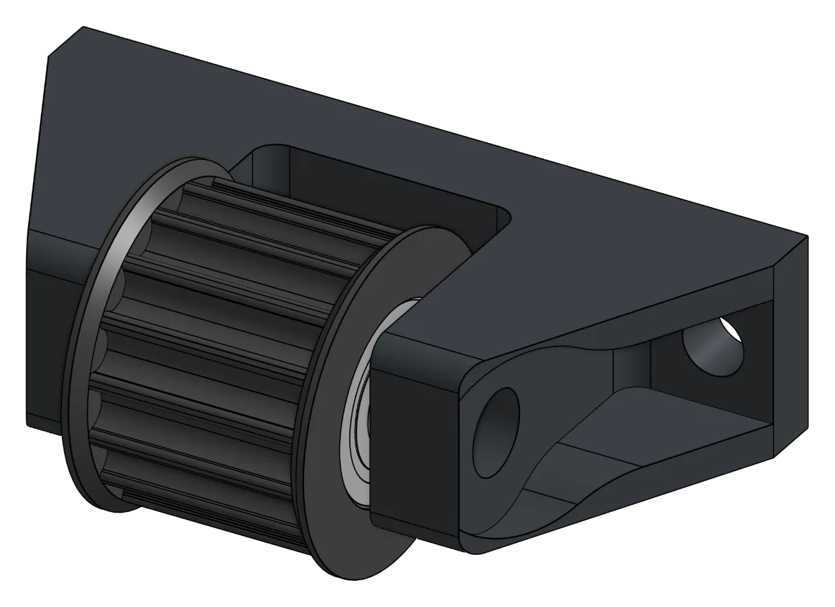
My first custom pulley versions lacked internal structure and were printed in PLA — weak enough that the pulley could actually be fractured by hand under relatively small loads.
I redesigned the pulley with significantly more internal structure and switched the material to carbon-fiber PLA.
A substantially stronger component capable of handling the belt tension — one of several parts iterated independently rather than triggering a full redesign.
The original belt clamps experienced tooth skipping when loaded.
I redesigned the clamps to provide better engagement with the belt.
The skipping problem was eliminated.
The pulley supporting the first stage initially deflected under the tension generated by the elevator belt.
I added a steel support bracket to reinforce the pulley.
The pulley no longer deflected under load.
The original motor mount was 3D printed in PLA and developed a crack during testing.
The mount was redesigned and replaced with an FDM-printed component.
A replacement mount that survived continued testing.
Additive and subtractive, together
The elevator’s aluminum plates were plasma cut, and many components were then machined on a mill for precise holes, mounting features, and interfaces.
Several components used hybrid manufacturing. The belt clamps, for example, combined a 3D-printed component with integrated belt teeth and a plasma-cut aluminum plate: the printed part provided the required geometry while the aluminum provided structural support.
Combining additive and subtractive manufacturing let components be iterated quickly without standing up an entirely new manufacturing process for every revision.
I performed the design, CAD, assembly, and testing; other team members assisted with manufacturing.
Camera integration
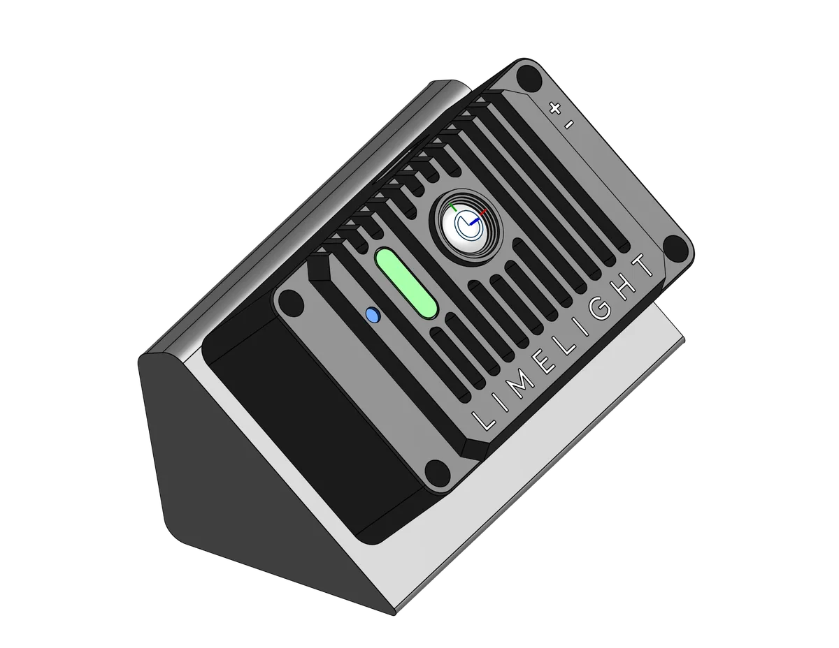
I also designed a custom camera mount as part of the elevator and robot architecture.
The original camera requirements called for separate cameras for intake detection and elevator-based targeting. During development I recognized that the elevator could not be operating in the same position as the ground intake, which made it possible to combine the functions — so I integrated both requirements into a single Limelight 4, reducing hardware and packaging.
The camera location was later moved to the opposite side of the robot for better visibility for reef localization and AprilTag targeting. That required coordinating the camera’s position with the elevator’s motion, robot packaging, field of view, wiring, and access to the camera’s controls.
Original → strategy change → final
Original configuration
Designed around scoring coral on the reef: variable vertical positioning for several scoring heights, with a third-stage carriage intended to carry the coral end-effector. Two motors and a synchronization shaft.
Strategy change
The team switched to scoring algae on the high net. With the net ~7 ft up, the elevator no longer needed to repeatedly hit several heights — it could be optimized around reliably reaching one high target.
Final configuration
The carriage was removed and the elevator’s extension was combined with the pivoting motion of the arm to reach the scoring position. A single motor at 20:1 drove both sides through the repurposed sync shaft, eliminating unnecessary components and adapting packaging to the new robot architecture.
Iterating parts, not the whole machine
The elevator was not developed through repeated complete redesigns. I iterated individual components as problems appeared during fabrication and testing:
- Redesigning belt clamps after tooth skipping occurred
- Reinforcing the first-stage pulley after it bent under belt tension
- Redesigning the belt tensioning mechanism after the cable-clamp method proved impractical
- Increasing the structural support of the custom pulley, and switching it to carbon-fiber PLA
- Replacing the cracked motor mount
- Removing the carriage after the game strategy changed
- Reworking the camera mounting architecture as robot requirements evolved
Once the individual components were resolved, the complete elevator was assembled and tested before deployment on the competition robot.
On the competition robot
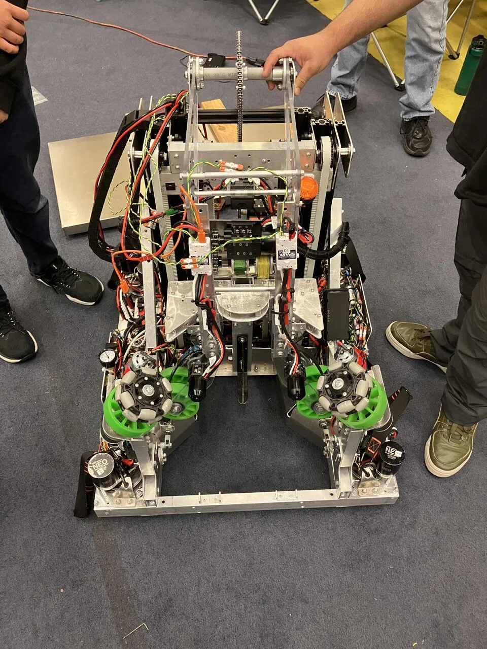
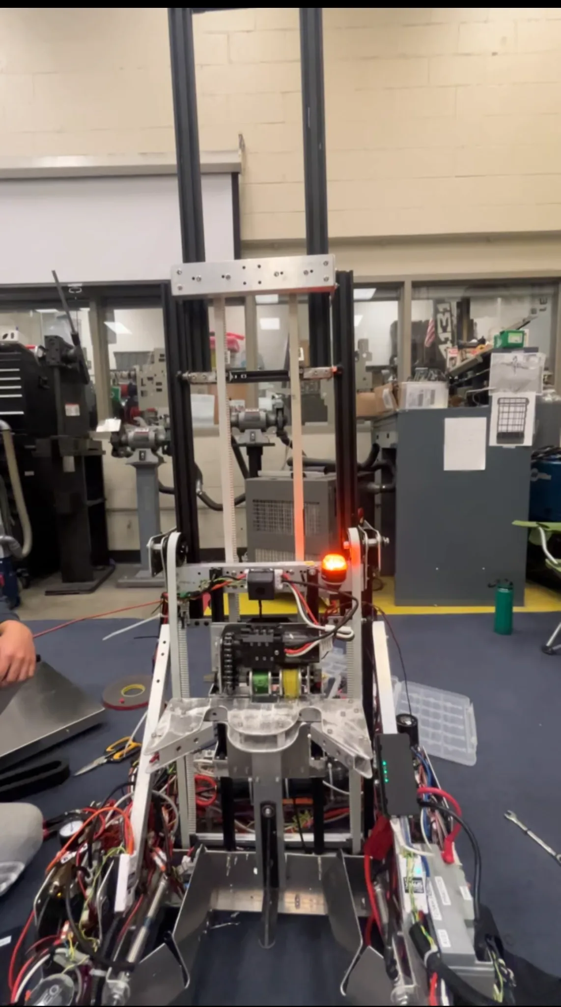
The completed elevator was successfully integrated into the competition robot and used as part of the final robot architecture. The final single-motor configuration provided sufficient lifting performance while reducing the elevator’s weight compared with the original two-motor design.
The mechanism combined three-stage cascading extension with the pivoting motion of the scoring mechanism to reach the ~7-ft-high algae scoring target — while remaining within the robot’s starting-height and total weight constraints.